Custom Torsion Springs
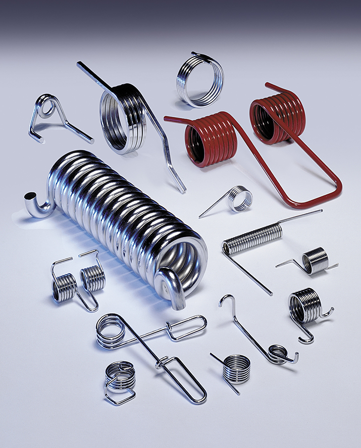
Special types of torsion springs include double torsion springs, heavy duty torsion springs, and springs having a space between the coils to minimize friction. Double torsion springs consist of one right-hand and one left-hand coil section connected together, and working in parallel. The sections are designed separately with the total torque exerted being the sum of the two.
Request a Quote for Custom Torsion Springs >>
Precision Torsion Springs
General Wire Spring uses some of the best coiling technology available to ensure that our torsion leg end positions are held to incredibly close tolerances for our precision torsion springs. The many possible end configurations are also tightly maintained. Precision torsion springs are commonly found in hinges, latches, handles, aviation, automotive, electronics, and the list goes on and on. At General Wire Spring, we employ the same quality and expertise in coiling torsion springs whether it is fine wire or heavy duty wire.
Heavy Duty Torsion Spring Details
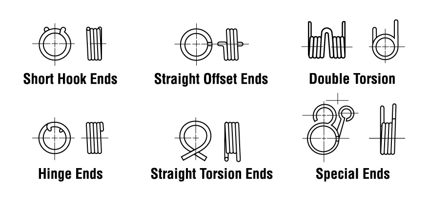
Type of Ends
The type of ends on torsion springs should be carefully considered. While there is a good deal of flexibility in specifying special ends and end forming, the cost may be increased and a tool charge incurred.
Heavy Duty Torsion Spring Installation
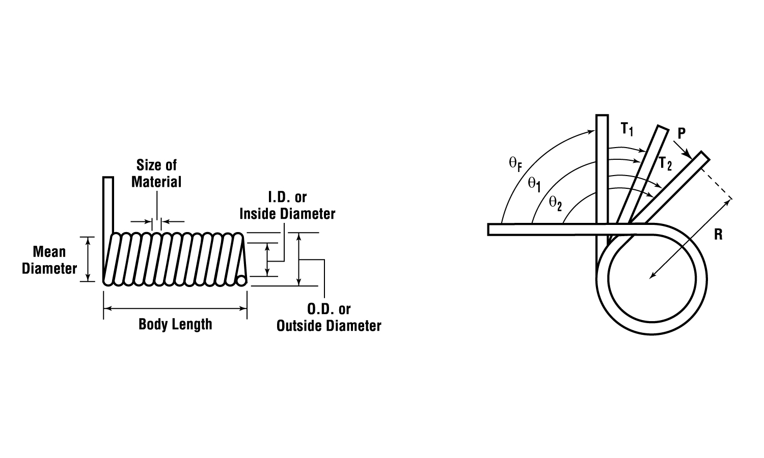
The type of ends and installation affect spring load and deflection as shown in Figure 1. All heavy duty torsion springs have three or more points of contact with at least two at the ends and one at the arbor. For clarity, the designer should specify the position of the contact points on the spring and their position relative to one another. (Figure 1 shown).

The basic formulas for torque or moment (M) and bending stress (S) used in designing torsion springs are shown below.
D = Mean coil diameter, in. (mm)
E = Modulus of elasticity, psi (MPa)
d = Diameter of round wire, in. (mm)
S = Bending stress, psi (MPa)
Nt = Number of coils
M = Moment or torque, ibin. (Nmm)
T = Deflection, number of turns or revolutions of spring
b = Width, in. (mm)
t = Thickness, in. (mm)
Technical Drawings for Torsion Spring Designs
The illustrations below are recommended as a guide in specifying torsion springs. The functional design characteristics of the spring should be given as mandatory specifications. Secondary characteristics, which may well be useful for reference, should be identified as advisory data. This practice controls the essential requirements, while providing as much design flexibility as possible to the spring manufacturer in meeting these requirements.