
Custom Compression Springs
 A compression spring is an open-coil helical spring that offers resistance to a compressive force applied axially. It is usually coiled as a constant-diameter cylinder. Other common forms of compression springs--such as conical, concave (barrel), convex (hourglass), or various combinations of these--are used as required by the application. While square, rectangular, or special-section wire can be specified, round wire is predominantly used in compressed coil springs because it is readily available and adaptable to standard coiler tooling. General Wire Spring specializes in the design and manufacturing of custom compression springs and heavy duty coil springs. Learn more about the types and sizing of standard springs below.
Compression Spring Design
To achieve sufficient strength for compressed springs, it is important to consider the level of stress in the design of custom springs. A metal coil spring should be stress-relieved to remove residual forming stresses produced by the coiling operation. Depending on design and space limitations, a compression spring may be categorized according to stress level as follows:
- Springs which can be compressed solid without permanent set, so that an extra operation for removing set is not needed. These springs are designed with torsional stress levels that when compressed solid do not exceed about 40 percent of the minimum tensile strength of the material.
- Springs which can be compressed solid without further permanent set after set has initially been removed. These springs may be pre-set by the spring manufacturer as an added operation, or they may be pre-set later by the user prior to or during the assembly operation. These are springs designed with torsional stress levels when compressed solid, and usually do not exceed 60 percent of the minimum tensile strength of the material.
- Springs which cannot be compressed solid without some further permanent set taking place because the set cannot be completely removed in advance. These springs involve torsional stress levels which exceed 60 percent of the minimum, tensile strength of the material. The spring manufacturer will usually advise the user of the maximum allowable deflection without set whenever springs are specified in this category.
Request a Quote for Custom Springs >>
Compression Springs Sizing & Specifications
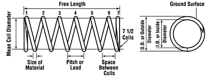
In custom compression spring design, the space allotted governs the dimensional limits of a spring with regard to allowable solid height and outside and inside diameters. These dimensional limits, together with the load and deflection requirements, determine the stress level and mechanical property requirements of the material. It is extremely important to consider carefully the space allotted to ensure that the spring will function properly, thereby avoiding costly design changes.
The illustration of spring dimensions below is recommended as a guide in specifying heavy duty compression springs. The functional characteristics of spring design should be given as mandatory specifications. Secondary characteristics, which may well be useful for reference, should be identified as advisory data. This practice controls the essential requirements while providing as much design flexibility as possible to the spring manufacturer in meeting these requirements.
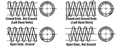
Spring Ends
Spring Materials
Another important design consideration is material. The spring dimensions and stress level specify the mechanical properties and material strength needed for the spring design. Our compression springs are available in a variety of heavy duty materials, including stainless steel springs. We provide custom springs in the following material types: